
what is transformer ?
Transformers are one such stationary electrical device. Which can reduce or decrease the alternating voltage without loss of energy. This reduces the voltage of the alternating current, so this voltage is called the alternating voltage. The transformer reduces the voltage without changing the recurring current.
transformer definition .
A device that reduces or exceeds the current going into an electrical device is called a transformer.
the invention of transformer .
theory of transformer.
 |
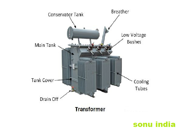
| transformer and parts |
parts of transformer
The transformer has three parts. Which has a metallic core and two windings. Which are made of very good conductive metals like copper. In the transformer, when alternating current is flowing in the primary coil, the magnetic field is created in the core. Whose value varies. The secondary coil is wrapped with this core. This also changes the magnetic flux passing through the secondary coil.Due to the change in magnetic flux due to the principle of electrical magnetic induction, the secondary coil starts flowing in the secondary coil.
The core in the transformer is in the middle. It is made of liminated steel plates. The leaves are made of types. There is a minimum air gap between all these leaves. Which reduces the vortex currents. The winding is wrapped around the core.
winding of transformer
 |
| transformer winding |
transformer conservator tank (dp oil tank).
Conservator tanks are used in high power transformers. They are small. These are upside down in the conservator tank transformer. The hot transformer oil cools and goes back.
transformer breather.
It is connected to the conservator tank. This transformer's breathing is used to breathe. The air inside and outside the transformer goes through the breather.
transformer valves .
Oil is poured into the transformer by valves. And the valve is pulled out.
steel tank of transformer
Steel tanks are an important part of the transformer. core winding etc. Everything happens inside it. It is cylindrical or cubic. It depends on the inner design of the transformer.
Calling tube of transformer.
transformer oil flows into the coling tube. It acts like a radiator and cools the oil.
thermometer of transformer.
The thermometer measures the temperature of the transformer oil and winding in the transformer. It sounds an alarm when it gets higher.
structure of transformer.
According to the picture, it has a flat rectangular core made of soft iron. The primary coil is made by wrapping copper wire on one side of this core. On the other side, it is made of secondary coil by wrapping copper wire.
 |
Here the reason for the core to be grounded is to reduce the effect of vortex currents.The alternating current to be replaced is applied to the ends of the primary coil and after switching, the ends of the secondary coil are used to obtain the voltage. It is worth noting here that the primary coil and the copper strands wrapped in the secondary coil determine whether the voltage is being reduced or exceeded.
That is, when the number of ferro in the primary coil is more than the secondary coil, a lower voltage is obtained. And when the number of ferro in the primary coil is kept lower than the secondary coil, the alternating current of higher voltages is obtained in the output.
mechanism of transformer.
The voltage of the alternating current has to be changed. Placing it at the ends of the primary coil. Due to which current starts flowing in primary coil, the value and direction of alternating current changes with time. Due to which a voltage is generated due to self-propulsion.

Therefore, the value of the flux generated in the primary coil will also change over time as a result of this the change in magnetic flux will pass through the secondary coil and due to the change in flux in the secondary coil a mutual carrying force is induced by reciprocal induction. This creates differences at the ends of the secondary coil. Which are obtained as output.
If the voltage of the primary coil is Vp.
Let the voltage of the secondary coil be Vs.
The number of ferro in the primary coil is Np.
If the number of turns in the secondary coil is Ns and the flux Q, then they are shown with the following relation.
Np / Ns = Vp / Vs = n = turns ratio
The alternating current can be increased or reduced with the help of a transformer. The transformer has a soft iron thin road. On which two coils made of thick copper wires are wrapped. In one horoscope, the number of ferro is less and in the other there is more number of rounds in the horoscope. The ends of the coil to which the alternating current source is added. It is called the primary horoscope.
transformer function.
When alternating currents flow in the primary coil. So magnetic fields are generated around it and magnetic force lines come out of the primary coil. Those magnetic force lines pass through the second coil. Therefore, there is a change in the magnetic flux passing through the second coil, so the induced electric force between the ends of the second coil is generated.
Number of ferro N1 in primary coil
And the number of turns in the secondary horoscope is N2.
The currents flowing in the primary and secondary coil are I1 and I2 respectively. And the input voltage Vp at the ends of the primary coil and the output voltage Vs at the ends of the secondary coil.
Rate of change in magnetic flux for primary and secondary coil for ideal transformer
dQ / dt is the time.
From Faraday's law of law -
Vp = Np dQ / dt Equation-1
Vs = -Ns dQ / dt Equation-2
Substituting equation-2 into equation-1
Vp / Vs = [-Np dQ / dt] / [-NsdQ / dt]
Vp / Vs = Np / Ns Equation -3
For the ideal transformer, the power of the primary and secondary coil are equal.
Pp = Ps
Vp Is = Vs Is
Vp / Vs = Is / Ip
From equation - 3 and equation - 4 -
Vp / Vs = Is / Ip = Np / Ns Equation-5
If the number of turns (Ns) in the secondary coil exceeds the number of turns (Np) in the primary coil, the output voltage (Vs) is greater than the input voltage (Vp). This is called high transformer.
If the number of turns in the secondary coil is less than (Np), the output is greater than the voltage (Vs). This is called a catabolic transformer.
Ideal transformer.
The efficiency of an ideal transformer is 100%. But not really. Energy is lost by doing something. Hence the efficiency of the actual transformer remains at 95%.

Types of transformer .
1. voltage transformer .
(a) step up transformer.
Step up transformer is used to increase the voltage of the current. The primary coil of the step up transformer has small number of turns of copper wires. And there are more in the secondary horoscope.
When we bring current for long distance. For example, a step up transformer is used in a city from a power station then the voltage of the current from the step up transformer increases, and there is no change in the value of the current.

Which are used to increase the transformer voltage. In Hindi, it is called a high resultant. There are fewer wire turns (Np) in primary winding. And in secondary winding (Ns) there are more wire strands. The number of wire turns in the first winding is less and the number of wire turns in the second winding is much thinner.
(b) step down transformer.
Step down transformer is used to reduce the voltage of the current. When power comes from the power station, then its voltage is reduced. The primary coil in the step down transformer has more copper wire spurs. And less in the secondary coil.

Then reduce the voltage. The voltage value of the current from the step down transformer decreases. And there is no change in the value of the current. Such transformers reduce the voltage. In its primary winding, wire thinning and wire turns are high. And the number of wire turns in secondary winding is less.
2 . phase transformer
(a)single phase transformer .
Single phase power supply of alternating current for one phase and neutral which transformer works. It is called single phase transformer. This type of transformer consists of inel coil and outer coil in the same core. In which it works as a primary and as a secondary.
This type of transformer is mostly used to step down the voltage and current value. Such as electronic devices used to step down and convert from rectifier to dc.

(b) three phase transformer
The transformer three phase power supply R.B.Y. And works for neutrals. It is called a three phase transformer. The three phase transformer can decrease or increase the voltage of the three phase power supply coming from the alternating current.
This type of transformer has three phase primary and three phase secondary winding. The cost of a three phase transformer is less than three single phase transformers of similar capacity. Its size is also small. This type of transformer power is used in transmission and distribution. It has three iron cores.

3. core transformer
(a) Iron core transformer
Transformers that have core iron. There are iron core transformers. Their efficiency is higher than air core transformer. A core for primary and secondary coil is made by adding thin leaves of lots of iron. The reason for being made of thin leaves is to reduce the vortex current.

air core transformer
The air core transformer has less mutual induction. Compared to iron and flue generation is higher than iron core. Because the medium is air. The vortex current ie eddy currents is very little or no.

instrument transformer
A transformer that is used to measure power. He is called an instrument transformer. Such as -current, voltage, power, frequency and power factor are known as instrument transformer. These transformers are mainly used to protect power systems with relays.
Types of instrument transformers.
(a ) current transformer (ct )
The transformer that is used to measure the supply of alternating current is called current transformer. All the operations of the power station are monitored by the current transformer itself. Its power supply can be measured by a clap meter. This type of transformer can be used in power systems to move the voltage from high level to low level with the help of 5A diameter.
Clamp meters cannot be used here. Because every device has a limit, how much current can be checked on it. For this reason, where we have to check more current, we have only one device. She ,current transformer हैं। All current transformers have a ratio, which we call the current transformer ratio. We know that the current transformer reduces the current,
so to find out how much current this city will give us, a ratio is written on the city, which is called the current transformer ratio..This type of transformer includes two winding such as primary and secondary. Current in primary winding is proportional to current in secondary winding. Because it generates current in secondary winding.
current transformer symbol
 |
| current transformer symbol |
current transformer Example.
there is a current transformer whose current transformer ratio is 1000/7. This means that when 1000 amperes current is coming out of the system. Then the current transformer will give us the output by converting that 1000 amperes into 7 amperes.
And if we have installed a current transformer of 1000/4 ratio in our system, then this current transformer will send 1000 amperes flowing across the wire to 4 amperes from the output wire.
(b ) potential transformer (pt )
The transformer that is used to reduce the voltage is called potential transformer. When unable to measure a high voltage. Then this transformer is used. A potential transformer reduces the high voltage and gives us a lower voltage in the output. potential transformer is used in the high transmission line. Because very high voltage is used in the transmission line.This transformer takes the voltage to a safe threshold value that can be easily measured by simple low voltage instruments such as voltmeters, wattmeters and watt-hour meters, etc.
") |
| potential transformer |
We know that from any volt meter, 33 kV or even 2 lakh 20 thousand KV, cannot check this much voltage. So at this time we use potential transformer to convert that high voltage into a low voltage, and later we will be able to measure the voltage from the potential transformer with the help of a voltmeter.Just as the current transformer ratio is written on current transformer , similarly the potential transformer ratio is also on potential transformer . Which is called potential transformer ratio.
A current transformer of 1000/5 converts 1000 amperes to 5 ampere. Similarly, potential transformer also has a ratio. If there is a pit and its ratio is 11000/110, then it means that the output comes out by changing the potential transformer 11000 voltage to 110 voltage.
Transformer based on usage.
Transformers that are built according to need and are used, such as - firstly to generate electrical energy or current, to manage it and then to distribute current.
The transformer is divided into 5 types based on usage.
(a) power transformer
(b) distribution transformer
(c) measurement transformer
(d) indoor transformer
(e) outdoor transformer
These transformer are described below -
(a) power transformer
Power transformers are those who work at a power generation station. They are meant to operate at high voltage. Their size is large, due to which the magnetic loss is also high.
(b) distribution transformer.
The job of distribution transformer is to distribute electrical energy or electricity. They share the power that is generated at the power generation. They are also engaged in our neighborhood. Some distribution transformers are also small. They are easy to change. And they have less magnetic loss. They do not load much.
(c) measurement transformer
measurement transformer current, voltage power etc. There are measures to measure. They occur at electrical energy generation sattion. And electricity is also there in the house.
(d) indoor transformer
These transformers are completely covered. They are used in the industry.
(e) outdoor transformer
These distribution types are transformers.


0 Comments
Write Your Comment
Emoji